Monday 13 September 2010

Completed the Crack!

After some waiting and a few false starts, the Crack has been completed. It was done over three sessions. Firstly, I must say that the instructions and build went very smoothly. The instructions provided by Bottlehead is first rate. The photos included were first rate, and I used them mainly to do the work and to check the work. The written instructions are very clear, but I found them actually a little verbose and the layout could be improved. In addition to the Crack, I also purchased the Speedball upgrade and completed that at the same time. The one and only problem was I soldered the wrong Transistors on the Speedball update. I did not pay attention that there are actually 2 types of small transistors.

The only other initial upgrade I applied was to change the output coupling capacitors from the supplied electrolytic to a 100uF Aeon paralleled with a Russian K40Y 0.1uF. The caps are big and was a little tight to fit, but it does. After the above fix, the amp fired up without problems. The voltages and resistance all measured as per the kit.

The first session was with my usual setup, using source from an old iPod. On first impression, the bass is really present and in your face. Almost to the point that can be felt. Amazing. The sound was very good indeed. There was a slight amount of hum present, but its level is quite low, and I didn't hear it until I looked for it. Otherwise, the dynamics are quite awesome and was really an enjoyable listen. This was more impressive given that it was unbroken in and it was using 'standard' components like a stock attenuator, connectors, and electrolytic caps!

Having a quick comparison with my Mini Max Millet left a few impressions. The bass on the Crack is much better to my ears. More body and more present. The sound is more lively and seems to be more 'dynamic' and less compressed. As I run the amp in, in the coming months, it will be very interesting to compare this with the other headphone amps.

It is also time to dust off my Maple Tree Audio Ear+ and fire that up. In tandem, I also purchased a TubeCAD 9-pin all in one, with the intent of making another headphone amp with that. So in the next year or so, I will have supposedly four quality headphone amps to compare!

Monday 17 May 2010

Tuesday 11 May 2010

6n6p Tube

  • The pin connection is the same as the 6DJ8, and also has a screen on pin 9.
  • Service life of 2,000 hours.
  • Heater 6.3V at 750 mA.
  • Gain of 22.
  • Curves look very linear.
  • Was the pre-cursor to the 6h30p tube.
  • Still very readily available and cheap.
  • http://www.klausmobile.narod.ru/testerfiles/6n6p.htm

6c19p SE Design Idea

Here is a quick idea for a simple 6c19p SE design.

  • Operating point at 210V at 45 mA with -80V at grid.
  • Say 300V at B+
  • Swing from -5V @ 40V @ 70mA to -160V @ 380V @ 25mA.
  • Loadline at 5k or 7k5 both have similar outcome.
  • Require a grid signal of around 50Vrms to drive to full power, with a bit of headroom to avoid A2 operation.
  • Assuming 2Vrms input, require a driver stage with a gain of around 25 minimum.
  • CSS loaded input stage could use C3g, 6n6p, 6DJ8/family, 6/12SN7, etc, a lot of tube choices in the medium mu grouping. Given the B+ of around 300V, operating the input tube at around 200V would be ideal.
  • Normal cathode biasing and capacitor coupling.

The great thing is that I have most of the parts lying around, with the exception of the power transformer. This can make good use of the Lundahl choke rated at 150mA, the CSS kit from K and K Audio and a few Jensen and Cerafine electrolytic capacitors. As usual, my enemy is time in getting around to hooking it all up. This would make a nice stereo amp. Maybe a schematic to follow.

This could even work for swapping out the output tube for a 45, by changing the bias capacitor and heater supplies. With B+ at 300V, the 45 could be 250V at 50V bias. Could work as a great convertible experimenter's amp.

Tuesday 4 May 2010

Key Facts of the 6C33C Tube

Here are some key facts and information regarding this tube. The information below is gleamed from tube datasheets, websites, forums and playing with the tube itself (but not in an electrical circuit yet).

  • In Cryllic, it is 6C33C. In transliterated English it is 6S33S.
  • Comes in two flavours, the vanilla (6C33C/6S33S) and the rugged version (6C33C-B/6S33S-V).
  • The main difference between the B and the normal version are the 'B' has lower Internal resistance and can withstand much more g forces in impacts and loads.
  • Rate life is around 1,000 hours, but in a non-military/extreme environment and operated well below maximums, this could extend out to 10,000 hours as suggested by some.
  • The tube is actually two triodes in one envelope. The cathode, plates and grid are internally connected in parallel. The heater is left separate, which can then be used singularly or both in a parallel or series connection.
  • The tube is designed to run with lower voltage (150-250V range) and higher currents (150-250mA range).
  • Very low internal resistance and a good candidate for OTL.
  • The heater takes a lot of heater power; either 12.6V @ 3.3A or 6.3V @ 6.6A. That is 41.58W.
  • The heater needs to turn on at least 2 minutes prior to B+ voltage. The longer the better.
  • The tube itself feels very rugged, sturdy and well built.
  • It was made in a number of different factories; Ullyanov, Svetlana and Poljaron.
  • It was first discovered in the West via a MiG-25 from a defector's plane.
  • Uses a special socket and has been suggested that it needs to be ceramic because of the high heat in the operation of the tube.
  • The pins of the socket generally need to be well ventilated and clean to ensure good cooling and electrical contact.
  • The tube runs hot and cooling and placement are critical to reliability and long life. Consider forced cooling, and considered passive cooling.
  • A link from Good Sound Club with lots of advice on the tube. Rather biased opinions, but nonetheless valid observations from someone who has used this tube extensively.

Monday 3 May 2010

Bottlehead Crack OTL

Just purchases the Bottlehead's new OTL headphone amplifier, the Crack . Seems like an interesting addition to my headphone system. It is relatively cheap, and looks to have plenty of room for upgrades/tweaks and expansion. Never used an OTL amp before, so it'd be interesting to build and compare this to the other headphone amps I have running.

The tube complement is very standard and readily available. The NOS prices on the two tubes, 12AU7 and 6AS7 are quite reasonable, moving up to the very expensive. But since it only uses one tube each, tube rolling may be an easy reality. Upgrades such as capacitor replacement (it looks 5 electrolytic can be replaced), CCS to the driver tube, resistor upgrades, sockets upgrades, etc. are possible.

Bottlehead seems to imply up to 4 weeks wait time, which is fine, as I am in no hurry to build. Over the last few months, I have come to the conclusion that headphone audiophile will be the main method of music enjoyment for myself. Mainly due to work and family arrangements. So, in the meantime, using my HD650, I will endeavour to build and listen to a wide a range of headphone amps as possible!

For reference, the following tubes may be suitable as substitutes.

12AU7 - ECC82, CV491, 5814, 6189, 5963, 6680, ECC802, E80CC and B749

6AS7/6080 - 7236, ECC230, 5998, WE421A, CV2523, 6336, 6520, 6h5c/6n5s, 6h13c/6n13s

6C33 Tube

Recently gained interest in Russian military surplus tubes, and inevitably the power tubes that tops the list include: GM70, 6C33 and GU50, etc. Here are some info on the 6C33 tube.

It appears there are two kinds of the 6C33; 6C33C and 6C33C-B. From reading various tech info, the 'B' designation seems to imply 'vibration proof, high reliability'. On the website above, the operation time (presume rated life) is shorter for the 'B' version at 750h rather than 1000h. The 'B' version seems to have lower internal resistance does have better acceleration and impact ratings. The curves for the two appear to be near identical.

Tuesday 9 March 2010

Lowther DX3

Recently, I purchased a pair of second hand Lowther DX3 from eBay and they arrived over the weekend. They arrived in good condition and appeared to be in very good shape. After a cursory checked, I hooked them up to my Zen EL84 amp. This was the first time that I turned the Zen on in my new house. The first thing I noticed was that the mechanical hum that was present in the power transformer was gone! This was a good start.

One of my debates in my head has always been, is 1 watt really enough? These Lowther were certainly going to confirm or deny this. Just using my iPod as the source, the amp was near silent with no music. A very faint hiss was heard only when you were so close to the speakers that you'd almost hit the cones. This was also good confirmation. I still noticed that the EL84 were running very hot on the heaters, with 7V plus. This still needs to be fixed.

The first cue of music, was my usual mix of favourite tracks that I was very accustomed to. The sound wasn't great. But mind you, they were simply placed on my dinner table. I had no chance to build any baffles. The good news was that the speakers worked without a problem. As you'd expect, there was little or no bass, thanks for a complete lack of enclosure. Obviously more thorough review will need to be done once they are in a proper enclosure.

My first impression was that piano notes and vocals did sound very natural and real. However, I noticed that there was something that I could only say was a 'Lowther Shout'. Now, I am no expert, but there are so many variables that may have caused this. To note, these Lowthers were the older styled without the rolled whizzer cone.

More thoughts and experiences to come.

Tuesday 2 March 2010

Different 45 Operating Points

Working out the operating points using the traditional ruler method and the RCA charts has been fun, but using TubeCAD's SE Amp CAD was not only much faster but produced far more information. The parameters are using a Tamura F5003 (Amorphous core US$600+ each transformer) with the plat at 202V biased at 35.8mA, results in an output of 1.3W and a distortion profile of; 2nd @ 1.7% and 3rd @ 0.1%). The input voltage swing required is 60Vp-p. If we wanted to maximise power without going into Class A2 (positive grid current), then the input swing would be 66V, and this results are 1.6W and a distortion profile of; 2nd @ 2.1% and 3rd @ 0.2%. According to SE CAD, %I max is 100%, %V max is 73% and %W max is 91%. Running the 45 reasonably hard. This will also be run with the Lundahl Amorphous core LL1620 or LL1623 output transformers. See the curves below.

Working on the assumption that we keep the 45 in Class A1 (i.e., no positive grid current), then the driver stage will need to deliver 23Vrms or 66Vp-p. If we assume that a 2Vrms signal is capable of being delivered by the preamp, the driver stage will need to have a gain of say 12x. This brings into contention a large range of tubes beyond the higher mu and high gm types (presently been considering C3g, D3a, 5842, etc.). Using a 1:2 transformer, either in the grid position (i.e., Lundahl LL1670) or as the interstage, would mean that the gain required by the driver itself is lowered to 6x. Opening up a range of DHT tubes. On the other hand, if a 2:1 interstage transformer was being used, then the driver stage will need a gain of 24x, BUT the impedance driving the 45 would lowered.

In one thought exercise, I might be able to get away with a 26 Tube into a 1:1 interstage transformer, and using the 1:2 step-up function of the Lundahl grid choke to provide a gain of around 15~16x. This would necessitate another Tentlabs Filament heater (to reduce hum) and probably far more attention to reducing microphonic and hum effects on the 26. Considering I already have starting a small stash of 26 tubes, this may be an interesting option. With various reports about the sound of the 26, this may be worth the effort.

At present, if using a 26 driver, the B+ for the 26 would be less then 200V, which means I can use a pair of 0C3/VR105 regulator tubes in series to provide a stable voltage for the 26. Perhaps a pair of 0D3/VR150 might be better if we were willingly to drop some voltage over a divider network. Consideration will be made to regulating the B+ for the 45 tube.

Friday 26 February 2010

The 45 Concept

For those who have read some previous entries in this blog, you will no doubt have read my ramblings regarding my directly heater triode amp. It began as the 300B story, and thus far, ended at the Electra Print DRD45. Having gained more insight into amp design and building, as well as more reading into the various standard reference books and Internet forums, I have concluded that the 45 is the tube to stay with. Helped in no small part to my 20+ 45 tubes. And in some twisted logic, I still hold that the 45 is a good tube for those wishing to trying different NOS brands and new stock. My reasoning to this; there are good range of NOS 45 available. They are easy to find and readily available on most stores and the price is still the sub US$100 per tube. The globle versions (UX145, UX245, UX345 and UX445) are much more sought after and range in US$150 to US$200 per tube. Whilst expensive they are still readily available. In terms of new production 45, I have only come across the Emission Labs and TJ brands. The range of available 45 is great and the NOS supply is still relatively affordable. This is in contrast to the 300B, 2A3, PX25/60, AD1, 50, 211, 845 and all the other DHT power tubes.

The 45 amp in broad design will be:

  • C3g driver tube. Either Triode of Pentode mode. To be reviewed.
  • Interstage Coupling. Using 1:1 or near interstage from either Sowter, Lundahl or Tango-ISO.
  • Fixed grid bias for 45. Using Tentlabs Negative Bias Module
  • Filament heating through Tentlabs filament module for 45.
  • Output Transformer is Electra Print 5K with 8R and 16R output. May consider changing to Tamura Amorphous core when the finances allow.
  • Passive PSU with 2 choke stages. Using a Lundahl LL1673/140mA common mode choke and an Electra-Print 5532 choke for each channel. All capacitors to be ASC Oil X386 types.
  • Rectifier tube 2x6AU4GT.

Most of the parts will be recycled from the DRD45 build that has yet to be done. This will be constructed as a stereo block with no attenuator.

Operating point of the 45 would be at the standard 220V with a -40V bias at 36mA onto a 5K load. Output should be around 1.3W, and will require the driver stage to provide around 40V of swing, or 80Vp-p or 28.4Vrms. If we have a sensitivity of 2Vrms then the driver stage needs to provide a gain of around 15x. An easy task for the C3g. The mu of the C3g is 40, so it might be worthwhile to consider using a 2:1 step-down interstage transformer. This may help reduce the reflected load and increase bandwidth. Being my first self designed amp, the above operating points may be completely wrong. However, it is a start, nonetheless. The other interesting note is that with the gain requirement of the driver stage of 15, it may open up possibilities of using an alternate driver tube, even using another DHT. Nothing ground breaking here.

Below are the heater requirements.

  1. 45 Tube: 2.5V @ 1.5A = 3.75 W per tube total 7.5 W.
  2. C3g Tube: 6.3V @ 370mA = 2.33 W per tube total 4.7 W.
  3. 6AU4GT Tube: 6.3V @ 1.8A = 11.34 W per tube total 22.5 W.

Total Heater consumption = 35 W (approx). More to come later.


Wednesday 24 February 2010

Further Adjustments on Millet

After using the amp for around 20 hours, I re-measured the tube bias. I found that it drifted to sub 10V. So in this whole process, I adjusted the B+ to 26.8V and thus biased each tube at 13.4V. This would result in around 12.6V on the heaters with the 10R heater resistor. I found that the sound improved and tighten up a lot. Over the course of the next 100 hours or so, adjusting for bias every 20 or so hours. I also took the chance to change the buffer bias to 110 mV. Regardless of these changes, the amp remains deadly silent with no hiss, hum or noise through the HD650. With my neighbourhood being very quite even during the day, it makes for a beautifully silent background.

It would be interesting that after the first 100 or so hours to play around with the tube bias and the buffer bias to see its effect on the quality of sound. It would appear from previous experiments that running the tube hotter and closer to its limits tends to produce a bigger and more dynamic sound. This amp would be an excellent platform to test such differences.

One of the delights of headphone audio is that you can really start to hear the music in a way that you cannot with speakers. Some faint spoken lyrics or background vocals becomes crystal clear. You can hear subtle noise in the background, like the creaking of piano pedals, or the pianist moving in the seat. Such minor details, though not affecting the overall enjoyment and appreciation of the music, tends to adds a new dimension to provide a much memorable experience.

Tuesday 16 February 2010

Mini Max Millet Part 3

Completion!
After a a few day's worth of soldering and assembly, the amp is finally working! As usual, the assembly work took longer than the PCB assembly itself. See some of the photos below for the progress builds. The biggest mistake I made was to solder the fuse clips on the wrong side of the board. Now I have to remove the PCB fully to be able to change the fuse. On hindsight, that may be a good thing, as a blow fuse would usually mean more of a problem down stream. So having to remove the PCB also forces me to have a quick check of the PCB itself.
The wiring for the volume control, crossfeed, etc was all done with solid silver wire and the use of tabs. Although this took a very long time, the results are well worthwhile. Using 24 AWG meant that I had to strip the teflon insulation off very carefully, otherwise any slight cut/scratch of the wire will cause it to break off when it is bent.

Biasing and setting up the amp wasn't too difficult. The B+ adjustment was straight forward, and I biased it to 25.6V, and it is now hovering around 25.58V. The diamond buffer bias is set at 100mA at present. Reading through the advice, I will leave this at this setting for a few weeks of use and then revisit after that. I want to let the various capacitors, resistors and transistors break-in. The tube bias was quite straight forward. At present, the channel imbalance doesn't seem too bad, and both channels are well balanced.

Once everything was biased and running for around a minute after that, I did the measure of the DC offset at the outputs. It was measured around 0.1mV. Not too bad at all! Everything appeared to be in good order. The heatsinks were getting warm, but only slightly so. With the diamond bias below their recommended levels, I'd assume that it isn't doing as hard work as it was designed to, and running cooler.
Once the final assembly was completed, I hooked them up with my test pear of cheap Sennheiser ear-buds. I first noticed a little hum, but it was not too loud. Connecting my test iPod up to the amp, I waited for the delay relay to kick in. Music! The sigh of relief was immense when sound was coming out of the ear buds! After letting this run in for about ten minutes, I powered off the amp to change to my usual cans, the HD650.
The sound, in short, was amazing. The hum had disappeared. Not sure whether that was from moving the temporary power cables around, or from a different headphone, or whatever, it was gone. Dead quiet, and this was late at night with very little ambient sounds. Fantastic! Powering through music, the first conclusions I made was; I did not like the crossfeed. At this time, I am not sure if the crossfeed was causing the first problem, or whether it was wrong wiring.
Using the crossfeed for the first time, I found that it muted the highs and made the sound very flat and even a little restricted. Turning it off made the sound more fuller and far more enjoyable. I was thinking that I probably should've tried the crossfeed before on another amp and would've saved many hours. Maybe, the caps need some time to open up, but at the moment, I think I will be listening without the crossfeed. I did not notice any widening of the soundstage or it moving from the off position. I think my ears/brain probably doesn't respond to the crossfeed at all.
Regardless of the issue mentioned above, the sound was amazing. The bass was awesome, very authoritative, and I have never really heard such clean and articulate bass before (headphones or speakers). It was almost scary. The mids was warm and clear and the highs crystal clear. All in all, a great sound. I think there will be no need for any bass boost. The balance at this moment, is very good to my ears.
At the end, I used both a Vitamin-Q and a Vishay MK1837 as a bypass on the output capacitors, and though only have less then 1 hour, the sound is already amazing. Looking forward to seeing them break in and get better over time. Part of me still wanted to try the Mundorf Silver-oil caps, but the leads were too thick, and I was in no mood to do any more modifications yet.
Overall, very impressed with the sound and quality. The remaining actions are:
  1. Remove Crossfeed
  2. Build legs to raise chassis off the ground to allow air flow inwards from bottom.
  3. Possibly install a few more LED to create a more glowing effect.
Enjoy some of the progress build Photos
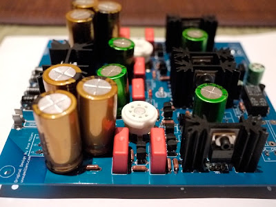
The photos below show the construction of the PCB with the most of the components installed. It also shows all the trimmers and terminal blocks on the bottom to allow for easy access and adjustment without having to remove the entire amp.


Below are the diamond buffer devices mounted on the heatsinks, ready for installation.


Below are some shots of the completed PCB. Note the Vitamin-Q mounted on the bottom of the board.


A few shots of the assembled amp. Note all the hook-up wires from the cross-feed to the switches and the various input and out connections. It was such a shame that I did not like the cross-feed and most likely remove it eventually.


Below the completed amp ready for power-up and first use.

Thursday 11 February 2010

DAC

After much reading in the last year or so, I have finally settled on a DAC Design to begin experimentation. The Analog Devices AD1865 family. To this end, I recently purchased from eBay the AD1865NOS-1.0 kit. As a start, I will hook it up with any modifications and let the unit run for a few months to let it break it and understand the type of sound this DAC is capable of. But the longer term plan is to modify the unit, potentially using a different I/V stage to draw more out of the chip. The long term plan would be to make a poor man's Audio Note DAC 4. This would most likely entail a CS8414 receiver, feeding into the AD1865. This would then be coupled to the tube gain stage via transformer, which the gain stage would be coupled to the world via another transformer. The intent would be similar to Ciuffoli's DAC-End, with the exception of an added transformer between the DAC and the tube. The power supplies at this stage would be Twister Pear Audio's Placid and TubeCAD's Janus.

Tuesday 9 February 2010

Mini Max Millet Part 2

Finally, everything is ready to go, every part, socket, tube, panel, etc is on-hand. See below the timber frame ready to receive the amp. Note that I am using a XLR input (as is my new standard for all my own equipment) rather than 2 RCA jacks. Also note the use of a lock TRS jack for the headphones. You can see below a few photos of the arrived panel on the timber chassis. The Front Panel Express panel is fantastic. The quality of finish and precision is very good. I will continue to use them for all future projects.


It was a tough choice, but as you can see, I decided to use the orange text on the panel. Combined with an orange LED under the chassis, I am hoping the whole unit will have a very warm colour glow during use, particularly at night, when I will be using it the most.


You can see below the partially completed crossfeed board. For the moment, I have only use stock caps, but I might change that some time in the near future. But the Panasonic ECQ caps are pretty decent. The trouble will be finding a cap of the required size to fit.

The capacitors used are Nichicon Muse for the large signal output capacitor with a Mundorf Silve/Oil as the high quality bypass cap. The power supply capacitors are Nichicon Fine Gold. The other parts are the stock parts as recommended on the MiniMax website.

Construction of the amp will begin after a final check to make sure everything fits. I anticipate that the construction will take around a full day, and I am eagerly looking forward to its completion. Over the last few years, I have built a small collection of 12AE6/12FK6/12FM6 tubes from a range of different manufacturers. By far the best sounding has been the Brimar. I am desperately trying to source more of the Brimar 12AE6A, but to date, no avail. Since I will be using Sennheiser HD650, I'd think that the higher gain tubes would be preferred and ultimately be the permanent tube in the amp. Look for the next part of progress build photos!

Monday 8 February 2010

Mini Max Millet Part 1

In the last few months, due to family, I have had a resurgent interest in Headphones. Having not really listened to my Sennheiser HD650 for a few months, I thought it time to dust them off and relax. During those months away from the headphones, I also took the task of upgrading my computer, during which I decided on a sound card upgrade. This was in the form of a Asus Xonar Essence STX. Whilst mainly functioning as a gaming PC, my music library is stored on this computer and shared over iTunes.

Naturally, I started to enjoy some headphone music through this setup. Initially, the sound was a little dark, but as the hours stacked up, became increasingly more open and less laid back. This combination is both easy on the ears and non-fatiguing. The sound stage for me was more forward, instead of in the middle of my head, it was at the front, near the forehead. The details that you get from headphones is so much more then through speakers. Although I find at this stage of the burn-in period, the Asus lacks some of the dynamics and 'sparkle' of my PPA headphone amp, I am sure that with time, this will improve.

Working on the premise that most of my audio enjoyment will probably come from headphones for the near future, I started looking into building a high quality headphone amp. Naturally my criteria was a tube based design. My first DIY Audio was Pete Millet's hybrid headphone amp. That was a rewarding build and a nice little amp. It combines a tube voltage gain and a IC buffer stage. Some would say combining the strengths of both technologies. However, having built that many years ago, the I decided it was time to see how that design has progressed.

Surely enough, there is a thriving community of Millet amp builders and has spawned several evolutionary designs. Looking through the forums and the net, it seems that most of the improvements lie in the output stage (employing a diamond buffer) and the biasing of the tube (i.e., using a CCS). Having the fore-sight to ensure that whatever I build be as reasonably compact as possible, I settled on the MiniMax Millet. Some of the progressions.

  1. Original Millet
  2. Max Millet
  3. Mini Max Millet
  4. Head-fi Iteration

Having ordered the various parts over the last month or so, the build is ready to begin. This time around, the chassis design will be a standard DIY Tube affair. 4 timber side walls with a metal top plate. The timber will be home made with a beeswax finish. The top metal plate has been laid out and ordered through Front Panel Express. The design allows for ventilation slots above the heatsinks with the tubes projecting past the panel. Further, most of the control are also on the top panel. In this design, I have also integrated the Tangentsoft's Modified Linkwitz Crossfeed.

Sunday 7 February 2010

Aikido Line Stage Build Begins!

Finally got around the designing and building the chassis for the Aikido line stage. Have a look at some of the photos during the planning phase. The chassis will be the usual timber sides and metal plate on top with the tubes and regulator heat sinks sticking through the top plate. The knobs and connectors are all on the front face.

I have decided to use XLR connectors in lieu of the 'Audiophile' type uber-expensive RCA sockets. It was actually the Eichmann plugs that gave me the inspiration. They were talking about the eddy currents, etc that happens when there is a sleeve type connection. And well, that does kind of make sense. But why not go one step further and remove ANY sleeve or ring type connection in the signal chain? The XLR are pin connection only, and being a professional audio product, designed for high numbers of inserts and removals. It is also silver plated connectors, with cable locks. All this had to around $10 each. Further, with the 3 pin standard connection, I can run stereo RCA, with the grounds tied together (which is what happens anyway inside the amp), and thus half the number of cables in the system.

You can see the generic layout of the chassis, with plugs all front access. Transformers and power stage at the back. 3 inputs and 4 outputs. The outputs will be arranged so that 1 will have a High Pass filter (around 150 Hz) and the other 3 will be full range with the RC f-3db point set around 1 Hz.

Close up of the DACT Stepped Attenuator. There will be enough room around for a potential upgrade to the Acoustic Dimension 41 step ladder attenuator.

Close up of the DACT Selector. It will switch both channels and ground. Since it is a 5 position switch and you can see I only have three inputs, it will be arranged that the two unused positions will act as mute function between each active position.

Some additional parts ordered to replace the standard kit components. Tantalum resistors in the important areas and Takman resistors in others. Note also the large Elna Tonrex caps for the heaters. Moulded Teflon sockets for all tubes and Obbligato film capacitors. The choice of output stage capacitors will be Mundorf Tin foil, with a potential for one of the output to have some kind of oil cap (Teflon, Copper, Silver/oil or Beeswax).

The power transformers, one for heaters (Hammond 185D12 6.3/12,6V 43VA) and one for B+ (Hammond 185E230 115Vx2/115Vx2 80VA). The IEC inlet has both dual fuse and EMI line filter. The heater transformer is slightly over-rated. With 5687 and 12AU7 as the tubes, the current draw should be around (5687 @ 12.6V = 0.45A and 12AU7 @12.6V = 0.15A) 1.2A total draw. With an available 3.4A supply from the 185D12, there should be enough head room.

Kids!

This is what happens when you leave speaker without protection from young kids! My no longer very nice Fostex FE127e dipole! Well, it may be just the excuse to try to phase plug replacement. And yes, it was done to both speakers, but luckily only to the front speakers, and not to the rear facing pair.