Monday 28 March 2016

Some photos...

Been busy, but working in the background and enjoying the setup...
The finished speakers. 

Temporary setup at back - note the ad-hoc wiring.

Crossover before soldering, generous layout - could've been more efficient. 

Another view of the cross-over. 

Monday 4 January 2016

Lowther OB Further Thoughts

You may have noticed that in my BSC, there is a capacitor, when the conventional BSC employs an inductor and resistor in parallel. I have used instead a conventional parallel notch filter to remove the baffle step hump. Now, the conventional theory is that the baffle step causes a 6 dB rise at a certain frequency and then above that point, it is generally a 3 dB rise. However, in the model, because the start of the rise of the baffle is around the point as the crossover, about 200 Hz, the 0 dB component of the BSC is part of the filtered part of the XO. Therefore, I reason that I do not need to use a standard BSC, because my baseline is the frequencies after the 6 dB hump, which is really only a 3 dB hump.

Combined with the room gain of the speaker, I am able to rune the Lowther without too much inline attenuation, beyond what the notch and crossover has already provided. Looking a 3R to equalise. However, with an L-pad, I should be able to dial that in as required.

Not sure if the above makes complete sense, except that once used in the model with the values, it produces a flat +/- 1 dB response, which is a pretty good start.

Further tweaking as yielding another set of values, this is primarily affecting the Lowther.

XO
100 uF and 4.7 mH

Notch
3.3 R, 1.5 mH and 68 uF

Baseline 2nd order passive crossover


Pretty much where it was before. It should also be noted that the values are not the conventional formulas. If we did that, the following is the predicted response.

Crossovers are at 200 Hz for Alpha and 250 Hz for Lowther. The notch filter is the same as above.

Lowther = 28 uF and 14.5 mH
Which will end up using 27 uF and 15 mH

Alpha 15a = 9.4 mH and 68 uF
Which will end up using 10 mH and 68 uF

Conventional 2nd order passive crossover

The benefit of the above is that the series capacitor is smaller for the Lowther and the series inductor is smaller for the Alpha. At the expense of the higher parallel inductor/capacitor value.

More tweaking to do. But at this moment, it feels like the 'baseline' option is the right option to go with.

Lowther OB BSC Revised

Have checked with the unused components and found close enough values for the BSC to remove the need to buy new components. So the new values are:
  • 3.3R Jantzen Superes Resistor 10W
  • 100uF Solen Capacitor
  • 1.5mH Jantzen Wax Foil 14AWG Inductor
The revised simulation with the above values - can always upgrade them later if this concept proves to be a winner! No change to the XO components.

Revised frequency response with amended BSC.

Sunday 3 January 2016

Lowther OB Continued

Did some more modelling, and started to apply a BSC to the design. From playing around, it seems that  2nd order passive cross over is going to be the easiest start, though I am playing with using the same components as that of a 1st order, so that I can add the parts to make it into a second order crossover. I have also played with turning room gain on and off. In either scenarios, the outcome is fairly similar, save the level of attenuation for the Lowther.

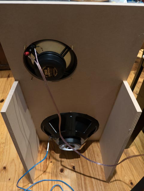
In both scenarios, I am using a 450mm wide and 1,000mm tall baffle, where the centre of the Lowther 800mm from the floor and 140mm from one edge. The BSC applied for this is with 3R 68uF and 1.5mH, all in parallel.

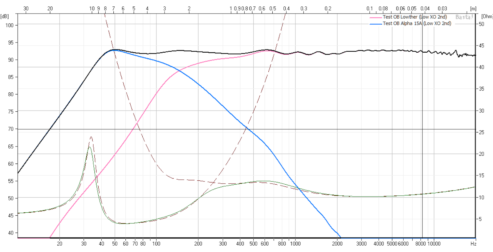
I have tweaked the passive cross over so that the values are now using 68uF and 8mH. The assumed resistance of the coil is 2.7R and the L-pad is 2R. The active crossover is 260 Hz for the Lowther and 150Hz for the Alpha. The charts are below. Both have the same speaker layout, room gain, etc.

Active crossover option.

Passive crossover option.
Part of this, I also wanted to see what would happen if I upgraded to a PM2a or PM5a, and they all perform very similarly in the modelling. I am certain that there will be small tweaks that can be done to optimize each driver, but the basic parameters are very similar.

Right now, the question is whether I should building the passive version, or finish building the Boozhoundlab crossover. I am thinking that the costs for the two are similar. Though I am thinking that the number of caps for the active is quite large (14 nos. in total), and the cost may be relatively high if one chooses the boutique caps. Also, long term, it will probably be easier to upgrade the passive components as part size is not a huge issue. Plus, I already have 1.5 mH inductors for the Beyma handy...

Parts for the Passive 2nd order:

68uF Capacitor x4 (Lowther BSC and XO)
220uF Capacitor x2 (Alpha XO)
1.5mH Inductor x2 (Lowther BSC)
8mH Inductor x4 (Lowther and Alpha XO)
2R Resistor x2 (Lowther L-Pad, though I will likely use the Fostex R80B that I have)

Parts of the Active 2nd order: (Excluding the PS and the JFETS)

0.1uF Capacitor x8 (Input and HP output coupling and XO)
0.033uF Capacitor x4 (XO)
10uF Capacitor x2 (LP Output)
Whole range of resistors and PS caps

Saturday 2 January 2016

Long time update....

What can I say, it has been two years since my last post, and what has happened in that time? Work, family and renovations... However, in that time, I did manage a few audio things, though I have not had the opportunity to blog about it. Hopefully, this coming year will be better. Here is a short summary of what has happened.

  1. Got myself an Fiio X3 Gen2 for travelling. This has been pretty good, but I have not been very happy with its pairing with my Earsonics. I am still awaiting my LH Geek Wave...
  2. Received the LH Geek Out SFi. I think I got it correct. It has been pretty good overall.
  3. Purchased and built the Elekit TU-8300R. Been fantastic Running them in with JJ 300B, Siemens ECC801s and James output transformers. Enjoying it and dreaming of upgrading it Elrog 300B and Noguchi Finemet output transformers.
  4. Built (finally) an OB with my Lowther DX3. Really enjoying them, but lacking bass. Which leads into the main contents of this post.
So, it took me all of 2 hours to build the OB for the Lowther, it was made using 16mm MDF, and tilted back 10 degrees with the baffle 450mm wide and 900mm high. It is nothing special. But the music that it makes is great, and really focused me on finishing these OB. I was reminded that I got the Lowther and Alpha 15a in 2011... Anyway, I started doing some simulations in Basta and got three working concepts. The three concepts are:
  • Passive first order crossover.
  • Passive second order crossover.
  • Active second order crossover.
Overall, I got the three options to look relatively similar in simulation. Note that all T/S data is by the manufacturer's supplied data and not through any measurement. I have also provided a fourth option using a higher crossover point using 1st order - this was done to keep values low and to use the crossover point to tame the baffle step, and obviate the need for a BSC. See the last option below.

Passive 1st order crossover
The parameters for this design are:

Lowther DX3
Crossover 68 uF
BSC 4R, 68 uF and 1.2 mH
L-pad of 8R

Eminence Alpha 15A
Crossover at 8 mH
'Room Gain' turned on with default settings.

Frequency response for passive 1st order crossover


Passive 2nd order crossover
The parameters for this design are:

Lowther DX3
Crossover 68 uF and 12 mH
BSC 3R, 68 uF and 1.2 mH
L-pad of 2R

Eminence Alpha 15A
Crossover at 10 mH and 200 uF
'Room Gain' turned on with default settings.
Reversed polarity.
Frequency response for passive 2nd order crossover.


Active 2nd order crossover
The parameters for this design are: The source voltage has been modified to allow for a 'flat' frequency response.

Lowther DX3
Voltage set at 2.83 V
2nd order at 250 Hz Q=0.707
BSC 4R, 68 uF and 1.2 mH

Eminence Alpha 15A
2nd order at 150 Hz Q=0.707
Voltage set at 5 V
'Room Gain' turned on with default settings.

Frequency response for active 2nd order crossover

Passive 1st order crossover (high crossover point)
The parameters for this design are:

Lowther DX3
Crossover 18 uF
No BSC
L-pad of 6R

Eminence Alpha 15A
Crossover at 2.7 mH
'Room Gain' turned on with default settings.
Frequency response for passive 1st order crossover - high crossover point.

Sunday 13 October 2013

Jordan JX92s MLTL

Well, I have finally got home, and in the past week or so, managed to finish the MLTL kits for the Jordans. I basically built it stock, but replaced the speaker binding posts with some gilded copper ones (from DIY Hifi Supply) and the internal wiring was with Amber HD 2 core speaker cable. I had an opportunity (reasonably rare) to listen to them for the first time last night for about one and a half hours. The amplification was Decware Zen using all Russian tubes and the source was my iPhone. Unfortunately, I did not have the time to set up the system.

Anyway, the room was a fairly large room - 8m by 6m with 2.4m ceilings. It was late at night, so very little ambient noise, but I also had to limit the noise as well. Technically, I had the volume control 90% on my iPhone to get to good levels, and it was probably a bit too loud given the time of night. But I didn't find the volume wanting. I still had a little spare, and the amp didn't show any signs of clipping. So, the 2W amp seemed to be okay for moderate levels of listening. Well, this confirms again, that I do not need ample amounts of power, and an amp in the 8W to 16W range may well be all that I need.

Onto the sound. Well, I was expecting something special, but I didn't get that. I supposed that there should be a longer break in time for the speakers, but the first time listening to these, didn't leave me wanting for more. Yes, the bass was present, but not as strong as I thought it'd be. And in my mind, the my initial thoughts with my (very well broken in and dustcap crumpled) FE127e closed bipoles was this: The details are much more clear and precise on the Jordan. The sound on the JX92s was cold and analytical, compared with the Fostex, which was warm and engaging.

Owing to the very short session and the ad-hoc nature of the first listening test, I will not form an conclusions. I will find a way of allowing them to break in for say 100 hours or so, before I firm up any decisions. What this has spurred me to do is to hurry up and get the Lowther OB up and running with the DX3 and the Beyma Coaxes...

The journey continues.

Sunday 8 September 2013

Beyma Crossover components

Here are the components that I ordered for the crossover for the Beyma 15XA38Nd Coax. I have chosen Jantzen components, in particular copper foil wax coil and Jantzen Superior-Z capacitors. The components are the same as per the standard Beyma crossover.


Jordan MLTL

I had purchased this set of MLTL enclosures from Decibel Hifi in Queensland many years ago, and never had the chance to put them together. In terms of the Beyma box and other projects, this is actually the quickest and easiest speaker to assemble to get some high quality speakers. So, here are the progress photos. I plan to seal all glued edges with butyl silicon, and eventually vinyl wrap the exterior. More progress to come when I return permanently back home in October. 


Sunday 25 August 2013

Beyma Coax 15XA38Nd Option - Ported Box Plan

The following is the outline drawing of the box with the port and using solid panels. I have re-arranged the bracing as well as the damping and insulation. The front panel is still made of two pieces of 12mm ply wood. There are two main reasons for this. The first being that I can get pre-veneered 12mm ply, but not 24mm. And the second being that the driver depth is 12mm, and thus I can flush mount the driver without have to rebate the edge.

Note that the design also allows for the port to be closed with a port cover. So that I can convert this between a ported and closed box design. In addition, I would like to experiment with varying the port between fully open and closed, that is, by stuffing it at various amounts. The estimated weight of this cabinet is around 46 kg without the driver and the binding posts. The speaker weights about 6.8 kg, and therefore the total estimate weight would be in the vicinity of 53 kg per speaker.

Beyma Coax 15XA38Nd Option - Ported Box

The enclosure speaker design requires the use of a Linkwitz Transform circuit to get a predicted flat response down to the low 30 Hz range. As an alternative, I modelled a ported version using the same enclosure size. The ported has an area of 250 cm3, and is back mounted about 150mm from the base of the cabinet. See below on the comparison between the two on Basta. I have chosen to predict the output at 8W power amp.
Comparison Between Closed an Ported.
The ported response is quite similar until 50 Hz, where it starts to diverge from the closed box scenario. It should be noted that the efficiency of the ported box can be seen, as the cone excursion is quite a bit less than the closed box when it gets to 20 Hz. I then further took the box design and put it into MJK's MathCAD spreadsheet. The spreadsheet used is the ML TQWT dated 11/07/07. The following are some screenshots of the results. The enclosure parameters are the same as per the drawing design in the previous blog entry.
Basic predicted response. 
Predicted response with Baffle step loss accounted. 
The final result with the BSC added, with the BSC being 20R and 12 mH.
I also modelled the same BSC in Basta and got the following result. It should be noted that in all the modelling, 8V or 8W was inputted as the amplifier power.
Basta simulation of the ported box with the BSC modelled as well to match MJK's spreadsheet.
Currently, I am working on an alternative cabinet using a 24mm solid thick wall, with dual 12mm front panel. This should make construction easier. In both designs, there is an assumption of internal box stuffing. Whilst Basta only allows for a percentage, MJK's spreadsheet allows for a more accurate assessment. In the design, I started at 8 kg per cubic meter. The resultant total weight of insulation was 1 kg and resulted in a reduction in the ripples in the response. I had originally place a thick layer of insulation between the bottom of the port and the base. But in MJK's simulation, it reduced the bass response significantly. And hence, the layer of insulation to the bottom of the enclosure has been removed. It also appears that over stuffing the box will result in reduced bass output.

The dilemma of practical construction will be ensure that the correct amount of stuff is placed, to reduced internal ripples and resonances but also not too much as to reduce the bass output. There will be lots of tweaking and construction sequence issues that will need to be resolved as this build progresses.