Showing posts with label Build Progress. Show all posts

Monday, 28 March 2016

Some photos...

Been busy, but working in the background and enjoying the setup...
The finished speakers. 

Temporary setup at back - note the ad-hoc wiring.

Crossover before soldering, generous layout - could've been more efficient. 

Another view of the cross-over. 

Saturday, 2 January 2016

Long time update....

What can I say, it has been two years since my last post, and what has happened in that time? Work, family and renovations... However, in that time, I did manage a few audio things, though I have not had the opportunity to blog about it. Hopefully, this coming year will be better. Here is a short summary of what has happened.

  1. Got myself an Fiio X3 Gen2 for travelling. This has been pretty good, but I have not been very happy with its pairing with my Earsonics. I am still awaiting my LH Geek Wave...
  2. Received the LH Geek Out SFi. I think I got it correct. It has been pretty good overall.
  3. Purchased and built the Elekit TU-8300R. Been fantastic Running them in with JJ 300B, Siemens ECC801s and James output transformers. Enjoying it and dreaming of upgrading it Elrog 300B and Noguchi Finemet output transformers.
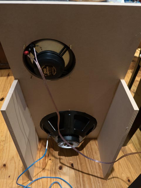
  4. Built (finally) an OB with my Lowther DX3. Really enjoying them, but lacking bass. Which leads into the main contents of this post.
So, it took me all of 2 hours to build the OB for the Lowther, it was made using 16mm MDF, and tilted back 10 degrees with the baffle 450mm wide and 900mm high. It is nothing special. But the music that it makes is great, and really focused me on finishing these OB. I was reminded that I got the Lowther and Alpha 15a in 2011... Anyway, I started doing some simulations in Basta and got three working concepts. The three concepts are:
  • Passive first order crossover.
  • Passive second order crossover.
  • Active second order crossover.
Overall, I got the three options to look relatively similar in simulation. Note that all T/S data is by the manufacturer's supplied data and not through any measurement. I have also provided a fourth option using a higher crossover point using 1st order - this was done to keep values low and to use the crossover point to tame the baffle step, and obviate the need for a BSC. See the last option below.

Passive 1st order crossover
The parameters for this design are:

Lowther DX3
Crossover 68 uF
BSC 4R, 68 uF and 1.2 mH
L-pad of 8R

Eminence Alpha 15A
Crossover at 8 mH
'Room Gain' turned on with default settings.

Frequency response for passive 1st order crossover


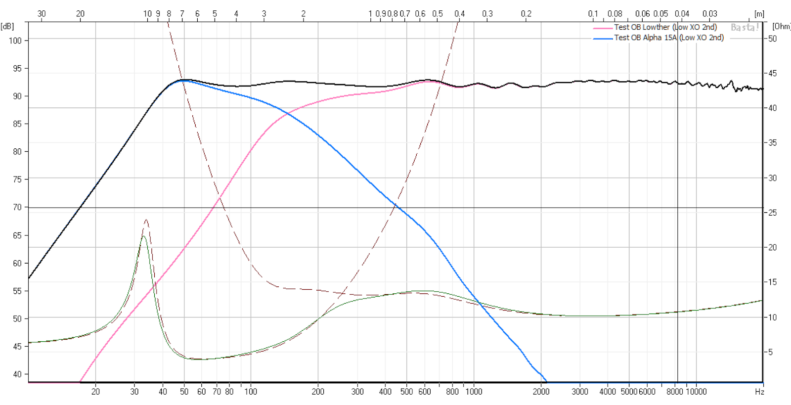
Passive 2nd order crossover
The parameters for this design are:

Lowther DX3
Crossover 68 uF and 12 mH
BSC 3R, 68 uF and 1.2 mH
L-pad of 2R

Eminence Alpha 15A
Crossover at 10 mH and 200 uF
'Room Gain' turned on with default settings.
Reversed polarity.
Frequency response for passive 2nd order crossover.


Active 2nd order crossover
The parameters for this design are: The source voltage has been modified to allow for a 'flat' frequency response.

Lowther DX3
Voltage set at 2.83 V
2nd order at 250 Hz Q=0.707
BSC 4R, 68 uF and 1.2 mH

Eminence Alpha 15A
2nd order at 150 Hz Q=0.707
Voltage set at 5 V
'Room Gain' turned on with default settings.

Frequency response for active 2nd order crossover

Passive 1st order crossover (high crossover point)
The parameters for this design are:

Lowther DX3
Crossover 18 uF
No BSC
L-pad of 6R

Eminence Alpha 15A
Crossover at 2.7 mH
'Room Gain' turned on with default settings.
Frequency response for passive 1st order crossover - high crossover point.

Sunday, 8 September 2013

Beyma Crossover components

Here are the components that I ordered for the crossover for the Beyma 15XA38Nd Coax. I have chosen Jantzen components, in particular copper foil wax coil and Jantzen Superior-Z capacitors. The components are the same as per the standard Beyma crossover.


Jordan MLTL

I had purchased this set of MLTL enclosures from Decibel Hifi in Queensland many years ago, and never had the chance to put them together. In terms of the Beyma box and other projects, this is actually the quickest and easiest speaker to assemble to get some high quality speakers. So, here are the progress photos. I plan to seal all glued edges with butyl silicon, and eventually vinyl wrap the exterior. More progress to come when I return permanently back home in October. 


Sunday, 25 August 2013

Beyma Coax 15XA38Nd Option - Ported Box Plan

The following is the outline drawing of the box with the port and using solid panels. I have re-arranged the bracing as well as the damping and insulation. The front panel is still made of two pieces of 12mm ply wood. There are two main reasons for this. The first being that I can get pre-veneered 12mm ply, but not 24mm. And the second being that the driver depth is 12mm, and thus I can flush mount the driver without have to rebate the edge.

Note that the design also allows for the port to be closed with a port cover. So that I can convert this between a ported and closed box design. In addition, I would like to experiment with varying the port between fully open and closed, that is, by stuffing it at various amounts. The estimated weight of this cabinet is around 46 kg without the driver and the binding posts. The speaker weights about 6.8 kg, and therefore the total estimate weight would be in the vicinity of 53 kg per speaker.

Beyma Coax 15XA38Nd Option - Ported Box

The enclosure speaker design requires the use of a Linkwitz Transform circuit to get a predicted flat response down to the low 30 Hz range. As an alternative, I modelled a ported version using the same enclosure size. The ported has an area of 250 cm3, and is back mounted about 150mm from the base of the cabinet. See below on the comparison between the two on Basta. I have chosen to predict the output at 8W power amp.
Comparison Between Closed an Ported.
The ported response is quite similar until 50 Hz, where it starts to diverge from the closed box scenario. It should be noted that the efficiency of the ported box can be seen, as the cone excursion is quite a bit less than the closed box when it gets to 20 Hz. I then further took the box design and put it into MJK's MathCAD spreadsheet. The spreadsheet used is the ML TQWT dated 11/07/07. The following are some screenshots of the results. The enclosure parameters are the same as per the drawing design in the previous blog entry.
Basic predicted response. 
Predicted response with Baffle step loss accounted. 
The final result with the BSC added, with the BSC being 20R and 12 mH.
I also modelled the same BSC in Basta and got the following result. It should be noted that in all the modelling, 8V or 8W was inputted as the amplifier power.
Basta simulation of the ported box with the BSC modelled as well to match MJK's spreadsheet.
Currently, I am working on an alternative cabinet using a 24mm solid thick wall, with dual 12mm front panel. This should make construction easier. In both designs, there is an assumption of internal box stuffing. Whilst Basta only allows for a percentage, MJK's spreadsheet allows for a more accurate assessment. In the design, I started at 8 kg per cubic meter. The resultant total weight of insulation was 1 kg and resulted in a reduction in the ripples in the response. I had originally place a thick layer of insulation between the bottom of the port and the base. But in MJK's simulation, it reduced the bass response significantly. And hence, the layer of insulation to the bottom of the enclosure has been removed. It also appears that over stuffing the box will result in reduced bass output.

The dilemma of practical construction will be ensure that the correct amount of stuff is placed, to reduced internal ripples and resonances but also not too much as to reduce the bass output. There will be lots of tweaking and construction sequence issues that will need to be resolved as this build progresses.

Saturday, 24 August 2013

Beyma Coax 15XA38Nd Option - Closed Box

This is my design option for a closed box design for the coaxial 15XA38Nd speaker. I have purchased this for over two years, I have not yet had the chance to open them since my departure from home. As I am relocating back home, I have decided that this is the first speaker that I should be building.
Cabinet Plan.
The following is the bill of materials. I have elected to use two layers of 12mm plywood as means of construction and only allowed for dampening around the inside faces of the cabinet. By using two layers of ply with a suitably, softer (i.e., less stiff) glue, I hope to reduce the panel resonance.

Bill of Materials
The results in a box with an approximate volume of 115 litres not included any of the dampening. I have run the simulation in Basta for this design and the following are the simulation results. The crossover is the same one as the standard Beyma crossover that can be bought separate from the speakers. The design is a relatively simple 2nd order crossover with a zobel network on the 15" low frequency driver. The approximate crossover point is 1.8 kHz. The components for the crossover that I have chosen is Jantzen Superior Z-cap, Jantzen Wax coil inductors and Jantzen Superes range.

The low frequency driver has a inductance of 1.5 mH and capacitance of 15 uF. The high frequency driver has an inductance of 1.5 mH and capacitance of 2.2 uF. The LF zobel is 8r2 and 8.2 uF.
Base Scenario.
Base Scenario with Linkwitz Transform.
Base Scenario with Linkwitz Transform and Room Gain. With this scenario, the source voltage is 6V.

So far, the predicted performance is pretty good. So the process now is to order the crossover components. The next step is to order the plywood cut to size followed by the damping materials. With the LT bass boost, the Xmax of the driver limits the power output to 4.5 W, which produces about 6 V and a cone excursion of 4mm. The estimated SPL at 1m would be around 103 dB.

Sunday, 14 July 2013

Beyma Modelled Design


After doing some very quick reading, I have assumed a room mode (in Basta) as per default. See the below plot which includes;

  • 1100 high, 500 wide and 400 deep box with vented box tuned to 33.3 Hz at 150mm diameter. 
  • Target of 175 litre volume with 40% Viso. 
  • Active filter at 2nd LP at 700 Hz and 2nd HP at 20 Hz.
  • Baffle Diffraction Effects on, but no BSC modelled.
  • Room Gain on

The result appears to be flat to 40 Hz at around 95 dB, -1 dB at 36.7 Hz and -6 dB at 28 Hz. Pretty close to the target I was aiming for. I am keep to the 4mm max, the power limit would be at 50 W, which would have an output of around 112 dB, or 110 dB at 35 Hz! I'd say that it is a pretty good simulation result.

With various options modelled, at 1 Wrms.

Modelled at max X-max.
Same as the first plot but with room gain turned off.
With the above, the 'mic' distance was far field. When it is changed to 4m near field (i.e., listening position), 50 W power would result in an average level of 100 dB, which is at the top end of my requirements. 16 W would get me to about 95 dB. What this means is that to adequately power this speaker will require an amp of between 16 W to 50 W.

Re-direction Part 2 - Speakers

Described by many as the heart of the system. Finding and/or designing the right speaker is probably the most important, as the approach I am taking is from the ears back. There is so much discussion and research on speaker design, and most of which is well beyond my capability to completed comprehend. However, from my research, there are number of key issues in obtaining the best quality speaker seems to be.

Crossover points - avoid if possible 250 Hz to 4 kHz, about 4 octave range. This is the most critical range of musical information and many describes it as the most critical point to avoid any crossover.
Use of neodymium or Alnico magnets seem to lead to higher quality of sound.
Use of cone materials that prevent breakup well outside (i.e., 2 octaves or more) the frequency range being played on the speaker.
Different speakers were designed to different enclosures, make sure the enclosure fits the speaker. General rules of thumb like using high Qts on open baffles, etc.
Important to have a smooth frequency response with good dispersion.

If we take the above first two items in our next design assumptions, we would be left with three speaker system. One for the LF work under 250 Hz, and one for the mid-range work from 250 Hz, and a HF unit crossing between 5kHz to 10 kHz that would take it to 40 kHz. The choices for the various drivers would be limited in the MR and HF areas. But once we take into consideration all the criteria, the range of speakers that can service in our requirements become somewhat limited.

However, in recent review of components and equipment, I have realised that I have amassed a range of speakers. FE207e, Lowther DX3, Saba green cones, Beyma Coax, Joran JX92s, FE127e, FT17H, and Alpha 15A. To be honest, to get good speakers cost money. And living in Australia, the cost of shipping of most speakers are quite sizeable. So the vein of being economically responsible, I will have to design a speaker system that uses one or more of the existing speakers in my collection. It appears from what I have, that it is mainly full range speakers, with the exception of the Beyma Coax. All the other speakers will mate well with a sub crossed at below 300 Hz or so, and can all probably do with a super tweeter (Fostex FT17H).

Therefore, it leads me to designing two speaker systems. One, the full range with sub and super compliment, and the other around the Beyma Coax. My next post will deal with the design of the Beyma Coax as a possible contender.

Thursday, 11 July 2013

Revised Assumption

Having read and reviewed more about my desired listening levels, I have come to the conclusion that 100 dB with 6 dB of overhead is probably a little too much. I believe that a value of 90 dB at the listening position is more sensible. Therefore, my assumption would change from a required combined speaker and amp able to deliver around 96 dB at 1 W at 1 m. Given a small buffer, the target range should be 95 to 98 dB. Of course it would be nice to have additional headroom of say 6 to 9 dB, but given my basic premise, I believe that the revised SPL levels are more realistic.

Monday, 8 July 2013

Verification of thought process


Since I will have a short trip home in the coming weeks, it is my plan to verify my second assumption, that is the 104 dB levels. My goal is to take out my pair of closed FE127e towers (yes, those with the front dust cap crumpled) and play them using my Decware Zen and then LM3886 Chipamp in the 100 cubic meter room. To hopefully negate the effects of the crumpled dust caps (yes, they are both now crumpled…) I will rotate them around and use the 'back speakers'. Wonderful thing about dipole and bipoles! The towers are made from 19mm thick Tasmanian Oak and have light filling. But the top and bottom are loose, leaving plenty of opportunity for tweaking.

The drivers are all terminated separately so that I can experiment with dipole, dipole and the parallel and series. I will listen to my favourite music, and see what levels are acceptable. If, and I stress if, they are suitable with the Zen, then I would see so many options opening up in both speaker and amp combos. If they are no loud enough with the LM3886, then I really need bigger amps and/or higher sensitivity speakers.

Through this, I will also experiment (hopefully) with the monopole, dipole and bipole arrangement. Which should give some further guidance as to my preferred arrangement. The source will be my QLS350 straight into the amps. I might try bringing in my HT sub, to see the effects of low end reinforcement. I will consider this my most important experiment. Speaker configuration, low-end reinforcement and power level combinations.

Note - to be honest, I am keen to see if I can get these to work well with the Zen, and then I can upgrade them to the F120A or even the new Jordan full rangers!

Sunday, 7 July 2013

Re-direction Part 1

After much pondering about my audio system, especially on my imminent return home, I have been through many of the same processes as I have done in the years prior to my departure from home. At the end of the day, it always came back to the same things as I have covered in my previous blog entries. Namely, back and forth between an all tube amp system or a tube plus SS system (for more power) and that of the speaker system. Which has oscillate between a high efficient system using horns, or a lesser (but still quite) efficient system using a traditional full range speaker driver.

Thus, I have come to a different process of deciding. A little background about my gear generally. In all my interests and hobbies, I plan and want to just have one - what is perceived by me as the ultimate, and then that is it. Not that it has to be the most expensive or best, but something in my mind that is no compromise. That is case for my cameras, computers, watches, cars, bass guitar, etc.. I have found that going around from low end to high end, ends up costing more money and time. But in the audio field, as I started with very little knowledge, and wanted the DIY route, it was natural that I take a longer journey.

In terms of headphones, I have I have almost reached that point. With my (soon to be built) C3g amp with HD650. Even with my existing range of built amps (about 6 in total) and headphones (over 4 high-quality pairs), I am more than a happy camper.

With speakers however, it has been a (very) long journey. Mainly due to moving houses, moving country and having children. But right now, I am in a better spot to move towards that end goal. So, instead of choosing an amp and speaker, I am going backwards, and choosing what I want in terms of sound, and then working back the audio chain. That is, desired sound, sound levels, speaker, amp and then source.

What I want is a system that is able to reproduce audio between 20 Hz to 40 kHz with high fidelity and ability to engage me beyond what can be 'objectively measured' - that is, it gives me enjoyment. What would I mean by high fidelity, I would assume low distortion and the frequency response to be generally smooth to within 3 to 6 dB in the frequency range, with a drop of say -6dB at 20Hz being acceptable.

Being honest, my listening room will never ever be larger than 7.0m by 5.3m by 2.7m high, so about 100 cubic meters. But at the moment, the listening room is 4.7m by 4.0m by 2.7m, about half the volume at 50 cubic meters. The system should be built for those two rooms.

The next question for me was how loud? I have been looking around the Internet, and measuring the values that I typically listen to. It seems that a value (for peak levels) of around 103 to 109 dB was about right, with most program levels being around 80 dB to 90 dB at the loudest normal levels.

In the larger room scenario, the listening position would be about 4m from the speaker, and the smaller room, it'd be 3m from the speaker. Which is not all that different. From this information, I would then determine the appropriate levels of speaker and amp performance to meet those dB levels. A listening position of 4m is about a 6 dB loss and at 3m, it'd be about 5 dB. In either case, the differences are marginal, so let's assume 6 dB loss due to speaker distance.

At this point, I will ignore room gain and other incidental losses, as they compound the complexity. For peak levels, let's assume for simplicity sake 104 dB. Therefore, the entire system of amp and speaker should be able to hit 110 dB. Therefore the first assumptions that are quantifiable are:

  1. Frequency Response range of 20 Hz to 40 kHz. -6dB at 20 Hz and within 3 to 6 dB over the range (that is plus or minus 1.5 to 3.0 dB).
  2. Combined maximum SPL levels of system should be 110 dB at 1 W at 1 m.

With the above in mind, we can now start to tinker with combinations of speakers and amps that meet the above requirements. The first for me is the philosophical combination of the two devices. So, if the speakers were to be 101 dB efficient, the amp would need to be at least 8 W in power. If the speakers were 92 dB, the amp would need to be at least 64 W in power. So, as the speaker efficient increases, the amp options open up for low powered tube amps. And as the speakers become less efficient, the ability to use tube amps rapidly decrease. The table below summarises the combinations.

Speaker Sensitivity // Amp Sensitivity
110 dB // 1 W
107 dB // 2 W (45 Amp)
104 dB // 4 W (2A3, AD1 Amp)
101 dB // 8 W (300B, KT88 SE, F2a Amp)
98 dB // 16 W (6C33, 211, 845, GM70)
95 dB // 32 W (211, 845, GM70)
92 dB // 64 W
89 dB // 128 W

Given my general interest in using Class A Tube amps, where generally SE tube amps limited to below 16 W or so, and PP tube amps around 32 W for Class A, it would appear that unless the speakers were to be at least 95 dB efficient, the use of tube amps would be not possible. Even with the rough limits mentioned above, the voltage and/or current requirements are quite large, limiting the ease of DIY. However, the choice in the number of amplifiers used has not yet been addressed.

Therefore, if I want to use tube amps (and I do) then I would have to find highly efficient speakers. This would generally rule out most of the speakers available. Focusing only on the mid-range (or pseudo full range) would limit the choice to high efficiency speakers such as 'traditional' full range family (e.g., Lowthers, Fostex, Supravox, etc.), horn loaded compression drivers, and other very efficient mid-range (generally) PA speakers.

Well, a longish entry, Part 2 of this will cover the issues dealing with speaker selection.


Sunday, 13 May 2012

Minor Updates

Well, it has been some time since my last post. Again, work, family and travel taking me away from audio and music. I am currently enjoying my mobile setup of iPhone 4 and my Earsonics EM4. At home, I am continuing to enjoy music through the computer to the Li Te DAC-AH and the through to the O2 amp. A lovely combination.

A few notes regarding the O2. I cut one of the gain resistors to reduce the gain to unity. I has allowed me to use more the volume control. Before, it was so sensitive there was horrible channel mismatch. But now, I can use it at 9 o'clock. Still not great, but better. Also the volume control on iTune is at 20%. Again, not great. My next task is to reduce the IV resistors and the gain of the opamp on the DAC to reduce gain even further. My aim is to have iTunes/Fidelio at 100% volume, and have sensible levels at my headphones at the 12pm/1pm position.

Have been thinking about the DAC, and how to build one with deliberately low volume, and the mating it direct to a LM based amp (something like 'The Wire' or TPA's Ventus. But have been designing that (or drawing that) and is taking a long time. Also not looking forward to the SMD parts soldering. Not sure when I will have the chance to put it all together, as my soldering gear is back home...

Anyway, not much to report on. Hopefully I will be able to do a few things like publish my 'design' (I use this very roughly cause I am really cutting and pasting...) on the TDA1543 with the Wire. I plan to use the O2 power stage (giving on battery +/-8V ish and on AC +/-12V ish) coupled to a standard TPA SPDIF receiver setup.
Tuesday, 25 October 2011

C3g Headphone Amp Progress

Here are some photos of the progress build of the C3g Headphone amp. As you can see, the TubeCAD Regulator PSU unit is assembled, and the various major components laid out. The key components: Acoustic Dimension 41 step attenuator, Lundahl LL1689 Amorphous core output transformer, TubeCAD PS-1 heater and HV regulator, two Hammond mains transformers, and massive IEC Inlet with filter, fuse and switch. All of this in a 16x8x3 Hammond aluminium case.


There are some time restrictions as I will be leaving shortly, and need to complete this within a few days, otherwise it will have to go in the post. Note that I am missing still the Yamamoto Loctal teflon sockets. Still, a lot of chassis work to be done, as well as testing, etc. 

Tuesday, 5 July 2011

Updates and WE396a Tubes Arrived!

After a few weeks of moving and settling in, I am not somewhat settled. Listening to the TU882R with the WE396a tubes right now. It is a good feeling to be mostly unpacked and most things setup. It is quite relaxing indeed. Anyway, in the last few weeks two notable events took place. Firstly, my order of 3 pairs of 396A tubes have arrived from Audio Tubes. I purchased from Brent;

  1. WE marked WE396a tubes. 
  2. National marked WE made 396a tubes.
  3. United marked and United made (in the UK) 5670 tubes.
They did attract a premium, being WE produced tubes and UK made tubes. I hope to get some photos up of these tubes, along with my three other types of 5670 tubes, once I find some space. It'd be good to do a sonic comparison of these tubes later on. 

The second item of note was my ordering of the Jordan JX92s MLTL kit from Decibel Hifi. They also arrived quite promptly from Brian in Queensland. I must say that they were a lot smaller then I thought they'd be, but nonetheless, still sizeable. From initial impression, the fit is good, and being MDF, should be easy to finish. Along with this order, I also put in for a set of 4 Eichmann Silver Bullet plugs. This is to connect the various computer output and DAC to the standard amps with use the RCA. As some long time readers will know, I prefer to use the XLR style connectors. But, when dealing with kits, inevitably, they are all RCA connections.

Anyway, back on track, I hope to be able to put these together in a few weeks. With a proper sized TV/main room, I am excited to see the JX92s perform. I plan to dress these up a little with some hardwood cladding over the MDF. This will both function as aesthetic, as well as adding additional stiffening and allowing me to fix some speaker cloth to it, to protect against the young ones. Again, long time readers can see my Fostex MLTL towers... Finally, regarding the Fostex, I plan to revive them by turning them around and adding a Speakcon on the current front side, and turning the 2 sets of binding posts into a hole for the vent. 

Lots to happen in the next few weeks, and now with a decent space to do some wood working, and space to place and use the speakers, I hope to be catching up with all the various speaker builds that have lay in abeyance in the last year or so. 

Saturday, 18 June 2011

C3g Headphone Idea


Here is something that I knocked up quickly as I was listening to the HD650 and Elekit headphone setup. This is in a similar vein to my D3a concept and shares many similar parts. I think this project would be very quick to knock up. This would make use of the TubeCAD Regulator PCB kit, making the build itself even more straight forward. The main reason for considering the C3g as well as the D3a tube are the various comments on the Internet regarding the consistency between various D3a samples. It appears that there may be a high sample variation between the tubes, and careful selection is required. The C3g, being a lower Gm tube, may have less sample variation. But time will tell, as I have to actually build the two amps first, to test the outcome. Again, this might work for other triodes as well.

Saturday, 4 June 2011

Repair of the Crack/Speedball

Finally got around to removing the board that was damaged due to my own fault. See the photos below. You can see a very small hole in the small blue resistor 237R. It measures over 4k now. One of the diodes also do not bias up at 1.4V. All parts removed and the through holes cleaned. I accidentally ordered the 2N2907 and 2N2222, rather than the "A" versions. Now, I have ordered the correct ones, and also a replacement 237R resistor. Should all arrive by next weekend, in time for re-installation. 


Wednesday, 11 May 2011

F4 Capacitors

Having reviewed the various options for the PSU capacitors around, I have decided to use either the Nichicon KG series (maybe Super Through), or the DNM T-Network capacitor (also here). In either instance, stick to a 10,000uF single for the first capacitor stage, followed by 2x 10,000 uF in the second capacitor, after the choke. I will aim to bypass the final stage with a low value, high quality 0.1~0.47 uF film capacitor. Maybe a Russian Teflon, or a paper in oil type. For safety, will be using 63V or higher voltage ratings. Finally, having reviewed how the F4 will be used, I no longer need to have a separate PSU supply for each channel, which reduces the cost and number of parts significantly. So in the above example, I'd be using 6 caps per F4, and I will need 12 in total, plus 4 film by-pass caps. Not sure if the above will work with the Chipamp PCB, as there are different cap positions. Also the KG don't all come in a snap-in PCB mount, actually, they are mostly in a termainl mount. However, the T-Network seems to have the right hole arrangements. Anyway, given I am moving house soon, all of this will have to be put on hold for at least 2 months until I settle in.

Monday, 9 May 2011

Heatsinks!

Had the opportunity to go down to Conrad Heatsinks today and pick up a pair of these puppies. Gee, they are big. 350x150mm in size. They are the MF35-151.5 and are rated at 0.21 C per watt for 80 C rise and weigh in at 2.46 kg each. See the Aleph PCB for size comparison. The guy was very nice and gave a good price to pick up and pay on the spot. These will be definitely in contention for the F4 build.

Saturday, 7 May 2011

Aleph 30

One of the projects that has been sitting on the shelf for some time has been the Aleph 30. I originally got the PCB from Chipamps about two years ago, and got most of the parts a year ago. Recently, due to my interest in the F4 amp, I decided it was time to finish this project sooner, rather than later. To that end, I purchased a Torodial transformer from Tortech, a 300VA dual 18V type. The only parts needed to complete this is a chassis and the heatsinks.

Regarding the heat sink issue, I have been exploring various options in my mind. Using the standard off the shelf heat sinks from someone like a Conrad Heatsink. Another option floating around is using heavy weight structural steel sections. I was thinking a 380PFC section cut to around 300mm in length. This would also form part of the top chassis. It weighs around 55.2 kg per meter, so a 300mm section would weight about 16.56 kg. Plenty of mild steel mass to sink the heat. But not sure if this would be a good thermal solution. More experimentation to come.


For those who are unfamiliar with a 380PFC, it is a parallel flange section of structural steel, much like a channel. It is 380mm in depth and comes in 6, 9 and 12 meter stock lengths in Australia. Because of my work, I can easily access these kinds of sections and in any length. It could make a wonderful, or disastrous solution.