After some more thought, it seems that there is great synergy between headphone amps and the F4 amp. In as much as, I can use all my headphone amps as the front end to the F4. In a simple way, once the F4 is built, each and every headphone amp also becomes a speaker amp. Of course, this is provided that they can output enough volts to drive the speakers. Looking through the F4 manual, the amp needs to out 10V swing or more (around 7 Vrms), with around 12 dB of gain, and moving towards 14V (10 Vrms) and 20 dB for lower efficiency speakers.
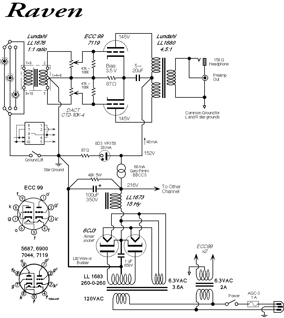
This then led me down a path of potentially exploring an even more extreme headphone amp - the Raven. This design is a fully differential single stage using shunt voltage regulation. The PSU is very similar to my D3a concept, and could be inter-changed. The prime difference is the current loading, the Raven requires 60mA per channel. However, with the higher spec'd chokes on hand, that may not be a problem.
This is something for me to consider as I embark on the D3a build. If I could make it modular enough, in terms of the PSU, then I could power the Raven with the same PSU unit. However, the primary cost of the Raven are the input and output transformers, and if I go for all Amorphous cost, the total cost would be around AU$1,000. A very tempting option indeed.
Showing posts with label Mosfet. Show all posts
Showing posts with label Mosfet. Show all posts
Thursday, 26 May 2011

Tuesday, 17 May 2011
Some more Pass Labs Build Links
Some more pages with great information on various Pass Labs projects:
- Aleph-X 100W
- Aleph 2
- Pass Labs A40
- Aleph X (PDF File)
Wednesday, 11 May 2011
F4 Capacitors
Having reviewed the various options for the PSU capacitors around, I have decided to use either the Nichicon KG series (maybe Super Through), or the DNM T-Network capacitor (also here). In either instance, stick to a 10,000uF single for the first capacitor stage, followed by 2x 10,000 uF in the second capacitor, after the choke. I will aim to bypass the final stage with a low value, high quality 0.1~0.47 uF film capacitor. Maybe a Russian Teflon, or a paper in oil type. For safety, will be using 63V or higher voltage ratings.
Finally, having reviewed how the F4 will be used, I no longer need to have a separate PSU supply for each channel, which reduces the cost and number of parts significantly. So in the above example, I'd be using 6 caps per F4, and I will need 12 in total, plus 4 film by-pass caps.
Not sure if the above will work with the Chipamp PCB, as there are different cap positions. Also the KG don't all come in a snap-in PCB mount, actually, they are mostly in a termainl mount. However, the T-Network seems to have the right hole arrangements. Anyway, given I am moving house soon, all of this will have to be put on hold for at least 2 months until I settle in.
Monday, 9 May 2011
Heatsinks!

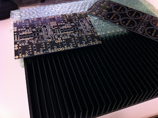
Had the opportunity to go down to Conrad Heatsinks today and pick up a pair of these puppies. Gee, they are big. 350x150mm in size. They are the MF35-151.5 and are rated at 0.21 C per watt for 80 C rise and weigh in at 2.46 kg each. See the Aleph PCB for size comparison. The guy was very nice and gave a good price to pick up and pay on the spot. These will be definitely in contention for the F4 build.
What to pair with the F4
The question of what to pair with the F4 current buffers is an important question that was asked in a forum, and I think it deserves some time to review. Currently, the best candidate would be the 45 DRD build. With a specified output of around 1 to 2W, makes a perfect candidate for F4. I also have a 16 ohm tap, which should ensure that there is sufficient voltage to swing the F4. In this configuration, I can be using a pair of F4 per channel to buffer both the HF and LF drivers. This frees up the choices available for either, as the speaker efficiency is not too critical.
On the other hand, I could attempt to mate it with my plethora of headphone amps, which in and of itself, would make an excellent experiment. That is, comparing different headphone amps on both speakers and headphones. And finally, I have an Aikido line stage sitting in parts, and that could itself also be a good front end. Either way, I think the flexibility that the F4 offers is great, and allows me to mix, match and experiment with different combinations.
Extending the notion of boosting a flea power amp, the F4 allows one to experiment with medium mu DHT or single stage DHT amps. Using something like a 30, with a mu of around 9 or a 01A, 26 or 10 with a mu of 8. There are so many possibilities...
Saturday, 7 May 2011
Aleph 30
 One of the projects that has been sitting on the shelf for some time has been the Aleph 30. I originally got the PCB from Chipamps about two years ago, and got most of the parts a year ago. Recently, due to my interest in the F4 amp, I decided it was time to finish this project sooner, rather than later. To that end, I purchased a Torodial transformer from Tortech, a 300VA dual 18V type. The only parts needed to complete this is a chassis and the heatsinks.
 Regarding the heat sink issue, I have been exploring various options in my mind. Using the standard off the shelf heat sinks from someone like a Conrad Heatsink. Another option floating around is using heavy weight structural steel sections. I was thinking a 380PFC section cut to around 300mm in length. This would also form part of the top chassis. It weighs around 55.2 kg per meter, so a 300mm section would weight about 16.56 kg. Plenty of mild steel mass to sink the heat. But not sure if this would be a good thermal solution. More experimentation to come.
Thursday, 5 May 2011
F4 PCB and some Parts

They have arrived. The 4 sets of PCB and the active parts for the F4 amp. The cost, US$126 for the semiconductor kits from Tech DIY and US$77.95 both including postage to Australia. Looking forward to getting the rest of the parts!
Tuesday, 3 May 2011
More F4 parts and update on TU882 Kit
Having looked around at the different suppliers and options for the source resistors for the F4, I think that the Mills MRA5 0R47 option would be the best. The Caddock MP915 requires a heat sink, and their other range of higher power resistors that do not require heat sinking, like the MV261 series are not easily found. Having made a personal note to avoid Parts Connexion, I have sourced Michael Percy for them, and will put together an order, along with the Nichicon KG that they stock.
Other information of note. The transformer selection for 2 channels of the F4 requires a minimum 300VA transformer, with two 18V secondaries. In my design, since each channel gets its own PSU, I will aim use a 250VA to 300VA transformer per channel. This should provide adequate headroom and maybe keep the load lighter, and thus the core cooler. From this, I can deduct 5A rated choke should be adequate, one for each of the positive and negative rails, instead of the parallel 0R47 resistors. The Hammond 159ZJ should do nicely. Now I need to get four of them. It also appears that amps with large farads of filtering capacitors may have a problem with the power on thump. So I will look into a soft start arrangement, and try to keep that to the primary side of the transformer.
I also contacted Victor about the hum and noise issue, and he suggested that I revert the amp back to the standard configuration, using the supplied pot and PCB to see if this problem can be removed. Smart idea. I will do that when I get the chance.
Other information of note. The transformer selection for 2 channels of the F4 requires a minimum 300VA transformer, with two 18V secondaries. In my design, since each channel gets its own PSU, I will aim use a 250VA to 300VA transformer per channel. This should provide adequate headroom and maybe keep the load lighter, and thus the core cooler. From this, I can deduct 5A rated choke should be adequate, one for each of the positive and negative rails, instead of the parallel 0R47 resistors. The Hammond 159ZJ should do nicely. Now I need to get four of them. It also appears that amps with large farads of filtering capacitors may have a problem with the power on thump. So I will look into a soft start arrangement, and try to keep that to the primary side of the transformer.
I also contacted Victor about the hum and noise issue, and he suggested that I revert the amp back to the standard configuration, using the supplied pot and PCB to see if this problem can be removed. Smart idea. I will do that when I get the chance.
Sunday, 1 May 2011
F4 Parts Sourcing
Currently looking around for the parts for the two F4 amps that I have on my mind. With the active devices already purchased, the choice is now narrowing for the remainder of the passives. I have elected to purchased 4x PSU PCB from Brian at Chip Amp as it allows a fairly straight forward build. I have use his kits in the past, quality and service is very good. The main question is how much to budget for this build. With the use of high quality resistors and capacitors, the passives alone for a 4 channel build will be close to the US$1,000 mark. The thought of diminishing returns start to play a part here.
PSU:
- Rectifiers - The specified ones from Brian are the MUR1560, which are 600V 15A ultra fast diodes. The schematic in the F4 manual states of 35A 200V bridge. The other option is an IXYS HiPerFRED Epitaxial diode DSEP 12-12A. The IXYS seems more favourable as it can handle higher voltages at 1200V and has a faster recovering time at 40 nS. Looking at Mouser, I also found IR 15EYX06, 30ETH06 and 15ETH06 interesting as their recovering times are 18, 28 and 22 nS respectively. This will require more research.
- Capacitors - I can find three main choices; Panasonic TSHA, Mundorf SI and Nichicon KG Snap in.
- Filter Resistors - This can either be a parallel group of 0R47 5W resistors, or a low value inductor. For the resistor option, Mills MRA-5 and the Caddock MP915 15W seems to be the most sensible options. But only the Mills is available in the 0R47, and that from Parts Connexion... This is important as it also is the resistor on the source (?) of the MOSFET and I would like to get them in bulk, since there will be so many, 14x4 = 48 in total. The use of a very low mH range inductor here as an alternative may be as much an economical one, as a design choice. the Hammond 159ZJ 10mh/5A or the 159ZL 2.5mH/10A are around US$26 each, where as Caddock resistors will be in the range of US$20 and Mills around US$10. The question is, will a choke be a better design choice.
- Transformer - Amplimo makes a suitable 500VA range. That should be more than adequate for 1 channel. But at Euro 94.96, it ain't cheap. Even moving down to the 300VA range, is still Euro 70.45 each. I will need 4 such transformers.
Signal:
- Resistors - For the source resistors, see above. The gate resistors and other signal resistors will be something like a Tantalum, Carbon composition or Charcroft type. The other supporting resistors will be high quality Takman, Kiwame, Amtrans or similar.
- Capacitors C1, C2 - Appear to be signal coupling capacitors, connecting directly to the gate resistors. Something more special needs to go in this place, possibly an electrolytic with a high quality film bypass. Nichicon ES Muse may be a starting point. Maybe a Mundorf Bipolar as an option. The board only has minimal space for the coupling capacitor, a Mundorf Tin or a small value copper in paper oil maybe possible. Given the feedback about Teflon capacitors and this design, I want to stay away from this combo, and keep towards a metal foil type.
- Capacitors C3, C4 - Seem to be power supply only, nevertheless, something like a high end Nichicon KZ or a Sanyo Os-con will do nicely.
Subscribe to:
Posts (Atom)